HX711 and load cell basics for reliable weight sensing
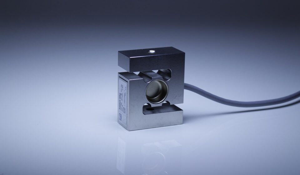
What the HX711 and load cell actually do
The HX711 and load cell combination is a common way to turn mechanical force into digital weight data in microcontroller-based weighing systems. The load cell produces a very small differential voltage as it bends under force. The HX711 then amplifies that bridge signal and converts it through a 24-bit analog-to-digital converter. In practical terms, the load cell is the sensing element, while the HX711 is the measurement front end that makes the signal usable for Arduino, ESP32, STM32, Raspberry Pi GPIO projects, and other embedded systems.
This pairing is popular because it reduces the analog design burden. Instead of building a low-noise instrumentation amplifier, precision reference, ADC, and timing interface from scratch, a designer can use an HX711 module, connect a Wheatstone bridge load cell, read two digital pins, and calibrate the output against a known weight. That simplicity does not remove the need for sound mechanics, careful wiring, and calibration, but it makes basic weighing systems much easier to prototype.
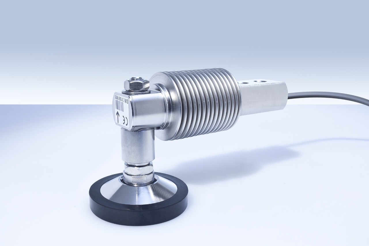
According to the Avia Semiconductor HX711 datasheet, the chip was designed for weigh scales and industrial control applications that interface directly with bridge sensors. SparkFun’s HX711 and load cell documentation also presents the module as a bridge between a microcontroller and a strain-gauge load cell. Used together, these sources are helpful in different ways: the datasheet defines electrical limits, while application guides show how those limits appear in real wiring.
For more smart hardware component explainers, visit Yingguoguo.
How a load cell turns force into a small electrical signal
Most hobby and embedded weighing projects use strain-gauge load cells. A strain gauge changes resistance slightly when it is stretched or compressed. Because that resistance change is extremely small, the gauges are typically arranged as a Wheatstone bridge. OMEGA Engineering’s strain-gauge material describes the Wheatstone bridge as a frequently used circuit for static strain measurement because it can detect small resistance changes with high sensitivity.
A four-wire load cell usually exposes the bridge as excitation positive, excitation negative, signal positive, and signal negative. A five-wire version may add a shield connection for electromagnetic interference control. Many modules and tutorials use the typical color pattern: red for excitation positive, black for excitation negative, green for signal positive, white for signal negative, and yellow for shield. However, color is not a standard that should be trusted blindly. Before soldering or crimping a production build, confirm the load cell datasheet or measure the wire pairs with a multimeter.
The signal level from a load cell is normally specified in millivolts per volt of excitation. A 2 mV/V load cell excited at 5 V, for example, produces about 10 mV at rated load. That is far below the range of a normal microcontroller ADC input. The HX711 is useful because it includes a low-noise programmable gain amplifier before the ADC, allowing it to resolve very small bridge changes without an external amplifier stage.
HX711 electrical features that matter in real projects
The HX711 is often described simply as a 24-bit load cell amplifier, but several details decide whether a design will behave well. The datasheet lists two selectable differential input channels. Channel A supports gains of 128 or 64, corresponding to full-scale differential input ranges of approximately ±20 mV or ±40 mV when AVDD is 5 V. Channel B has a fixed gain of 32 and a wider approximate full-scale input range of ±80 mV under the same AVDD condition.
The chip also supports selectable output rates. With the internal oscillator, the common choices are 10 samples per second and 80 samples per second. The faster mode is useful when response time matters, but the datasheet’s electrical table shows higher input noise at gain 128 in the faster-rate condition than in the slower-rate condition. For a stable scale, 10 SPS is often the safer starting point. For force feedback or dynamic measurement, 80 SPS may be acceptable if the application can tolerate more filtering work.
| HX711 feature | Practical meaning | Design note |
|---|---|---|
| 24-bit sigma-delta ADC | Converts small bridge signals into digital counts | Resolution on paper does not equal final scale accuracy |
| Channel A gain 128 or 64 | Best suited to typical low-output load cells | Gain 128 is the common starting point |
| Channel B gain 32 | Wider input range but lower gain | Often less convenient for the main load cell reading |
| 10 SPS or 80 SPS | Tradeoff between stability and update speed | Use 10 SPS for scale-like readings first |
| Two-wire digital interface | Uses DOUT and PD_SCK instead of I2C or SPI | Library timing should be reliable on the chosen MCU |
| Power-down support | Can reduce consumption in battery projects | Wake-up and settling time still need to be handled |
The supply range also deserves attention. The HX711 datasheet specifies an operating supply voltage range of 2.6 V to 5.5 V for the chip, while many breakout boards publish a module operating range near 2.7 V to 5.5 V. In embedded practice, the module supply, microcontroller logic level, load cell excitation, and ground reference should be treated as one measurement system rather than separate parts.
Basic wiring pattern for one load cell
A straightforward HX711 setup has two sides: the load cell side and the microcontroller side. On the load cell side, excitation positive and negative power the bridge, while signal positive and negative carry the small differential output into the HX711 input pair. On the microcontroller side, DOUT sends data to a GPIO pin, and PD_SCK is driven by another GPIO pin as the serial clock and power-down control.
A typical wiring plan looks like this:
- Load cell excitation positive to E+ or VCC bridge terminal on the HX711 module.
- Load cell excitation negative to E- or GND bridge terminal.
- Load cell signal positive to A+ or INA+.
- Load cell signal negative to A- or INA-.
- HX711 VCC and GND to the microcontroller supply and ground recommended for the module.
- HX711 DOUT to one microcontroller input-capable GPIO.
- HX711 PD_SCK or CLK to one microcontroller output-capable GPIO.
The exact terminal labels vary by board. Some boards use DT instead of DOUT, SCK instead of PD_SCK, or SIG+/SIG- instead of A+/A-. The important rule is to match the electrical function, not the label style.
If the reading goes negative when weight is applied, the system is not necessarily broken. The signal polarity may simply be reversed relative to the library’s assumed direction. Swapping A+ and A- or using a negative calibration factor can correct the direction. The cleaner choice depends on whether the hardware layout is already fixed.
Calibration is not optional
An HX711 module does not know the capacity, sensitivity, mounting orientation, or preload of the connected load cell. Calibration converts raw ADC counts into a meaningful unit such as grams, kilograms, pounds, or newtons. The general method is simple, but accuracy depends on consistent setup and measurement practice.
- Mount the load cell in its final mechanical position, not loose on a bench.
- Power the system and allow a short settling period.
- Take a zero reading with no applied load except the platform or permanent fixture.
- Apply a known calibration mass within the intended operating range.
- Calculate or adjust the scale factor until the output matches the known mass.
- Repeat at another weight to check linearity and mechanical behavior.
- Store the zero offset and calibration factor if the system must restart without manual setup.
Common Arduino libraries, including the widely used bogde HX711 library, expose functions for tare, scale factor setting, raw readings, averaged readings, and unit conversion. Those library functions are conveniences; they do not replace physical calibration. A calibration factor copied from an example sketch is only an example value, not a universal constant.
For better results, choose calibration masses near the region where the device will be used. A kitchen ingredient scale, a small force platform, and a bin-level monitor may all use the HX711, but their useful ranges and tolerances are different. Calibrating a 50 kg load cell only with a very light object can leave the most important part of the range poorly verified.
Mechanical design often limits accuracy more than the chip
Many unstable HX711 projects are blamed on code when the real cause is mechanical. A load cell must bend in the intended direction, at the intended point, with a force path that matches its design. If a bar load cell is clamped incorrectly, if the platform rubs against an enclosure, or if the load is off-center, the ADC can faithfully report a bad mechanical signal.
Designers should treat the load path as part of the sensor. Use a rigid base, avoid side loads unless the load cell is rated for them, and protect the element from overload. If the project uses multiple single strain gauges or half-bridge sensors, the wiring must form a correct Wheatstone bridge before the HX711 can measure the combined output. SparkFun’s load cell documentation notes that multiple single strain-gauge load sensors can be combined into a Wheatstone bridge arrangement, a layout similar to what is used in many bathroom-scale style platforms.
Temperature is another practical limitation. The HX711 datasheet provides input offset and gain temperature drift figures under specified conditions, but the complete scale also includes load cell material behavior, adhesive properties, mounting stress, and environmental changes. For casual projects, a manual tare before use may be enough. For unattended equipment, drift testing over the expected temperature range is more important than adding more decimal places to the display.
Noise, drift, and troubleshooting checklist
Noise in a weight-sensing system can come from electrical, mechanical, and software sources at the same time. A useful troubleshooting approach is to separate them instead of changing everything at once.
| Symptom | Likely area to check | Practical action |
|---|---|---|
| Readings jump randomly with no load | Wiring, grounding, EMI, loose terminals | Shorten wires, secure connectors, verify shield and common ground |
| Reading changes slowly after tare | Mechanical creep or temperature drift | Let the structure settle and test after warm-up |
| Output is stuck near maximum or minimum | Input saturation or wrong bridge wiring | Check A+/A-, excitation, and load cell damage |
| Weight direction is reversed | Signal polarity | Swap signal inputs or adjust calibration sign |
| Good reading on bench, poor reading in enclosure | Mechanical interference | Look for rubbing, twisting, side load, and cable pull |
| Fast mode looks unstable | Sampling-rate noise tradeoff | Return to 10 SPS or add averaging and filtering |
Software filtering can help, but it should be added after the hardware and mechanics are stable. Averaging five to twenty samples, using a moving average, or rejecting obvious outliers can make displayed values easier to read. However, filtering also adds latency. A postal scale, dosing system, or robotic gripper may each need a different compromise between response speed and stability.
When to use the HX711, and when to consider alternatives
The HX711 is a strong choice for low-cost scales, educational projects, bin weight monitors, small process-control devices, and prototypes where a simple two-pin digital interface is acceptable. It is especially attractive when the sensor is a standard bridge load cell and the required update rate is modest.
It may be less suitable when the project needs a standard I2C or SPI interface, synchronized multi-channel sampling, higher sample rates, extensive diagnostics, or documented performance across a certified measurement chain. In those cases, a different load-cell ADC, an instrumentation amplifier plus precision ADC, or an industrial weighing transmitter may be more appropriate. The tradeoff is cost and complexity: the more the measurement matters legally, financially, or for safety, the less a bare hobby-style module should be treated as the complete solution.
The bottom line is straightforward: the HX711 makes load cell measurement accessible, but it does not make every scale accurate by default. Good results come from matching the load cell capacity to the task, wiring the bridge correctly, using the HX711 within its electrical limits, mounting the mechanics properly, and calibrating against real known weights.
Frequently asked questions
Can one HX711 read multiple load cells?
Yes, but not by simply putting unrelated full-bridge outputs in parallel. Multiple single strain gauges or half-bridge sensors can be wired into one complete Wheatstone bridge with the right combinator circuit. Multiple independent full-bridge load cells usually need careful summing hardware or separate ADC channels, depending on the required accuracy.
Is 24-bit resolution the same as 24-bit accuracy?
No. The 24-bit ADC describes the conversion format, not the finished scale accuracy. Noise, load cell quality, excitation stability, mechanical mounting, temperature, calibration mass quality, and filtering all reduce practical performance.
Should I use 10 SPS or 80 SPS?
Start with 10 SPS for normal scale readings because it is usually easier to stabilize. Use 80 SPS only when update speed is more important and you are prepared to manage additional noise through layout, mechanics, and filtering.
Why does my HX711 reading drift after zeroing?
Drift can come from load cell creep, temperature change, unstable mounting, cable movement, electrical noise, or insufficient settling time. Recheck the mechanical fixture before assuming the library or microcontroller is the problem.
Can I power an HX711 module from 3.3 V?
Many HX711 breakout modules can operate from a 3.3 V-class supply, but verify the specific board documentation. The chip datasheet gives a low-voltage operating range, while module regulators, pull-ups, and layout choices can affect practical compatibility.